
37° Flare and 24° Bite-Type Connections: Standards, Seals, and Use Cases
HGW Hydraulics on May 31st 2022
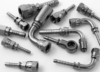
Two metal tube connections can use a nut and sleeve yet form their seals in very different ways. A 37-degree flare fitting seals against a prepared flare at the end of the tube. A 24-degree bite-type fitting uses a cutting or gripping ring that engages the tube outside diameter as the nut is assembled. That difference affects tube preparation, inspection, service, and whether parts that look similar can be combined.
These families appear on industrial, construction, agricultural, test, mobile, and specialty equipment. The right identification comes from the governing standard and sealing geometry, not from a general label such as “compression fitting” or “hydraulic hose end.”
Start with the connection standard and the place it seals
SAE J514 covers widely used hydraulic tube fittings, including 37-degree flare and flareless configurations. SAE J1453 covers O-ring face seal connections, which are a separate flat-face O-ring family. ISO 8434 includes related metallic tube connection standards. DIN, JIS, military, and manufacturer-specific requirements may define other dimensional or tolerance details.
The standard matters because thread size alone does not identify the joint. The thread usually provides clamping force; the flare seat, ferrule bite, O-ring face, or other prepared surface contains the fluid. Mixing a nut, sleeve, body, or tube end from a different system can produce thread engagement without a valid seal.
Material and configuration also influence published ratings. Straight steel fittings, shaped bodies, stainless components, tube wall, and connection size may have different limits. Use the rating for the exact part and assembly rather than applying one pressure number to an entire fitting family.
How a 37-degree flare joint carries load
The end of the tube is formed into a 37-degree flare. A sleeve supports the back of that flare, and the nut draws the tube and sleeve onto the male cone. The metal-to-metal contact at the matching seats forms the primary seal.
Preparation quality is visible at the flare. The tube should be cut square, deburred, and formed with the correct tool without splits, uneven wall, excessive thinning, or tool marks across the sealing surface. The nut and sleeve must be placed on the tube before flaring. Tube material, outside diameter, and wall thickness must fall within the applicable forming limits.
The sleeve spreads mechanical load behind the flare and helps manage vibration. Correct assembly pulls the seats together without using the nut to correct severe tube misalignment. If a line has to be forced sideways to start the thread, the installed stress can distort the flare or keep the seats from contacting evenly.
SAE 37-degree flare connections are common in U.S. hydraulic equipment because the family is available in many sizes, materials, and body shapes. JIC is the familiar industrial term. The same 37-degree angle also appears in AN-style connections, but equal seat angle does not make every JIC and AN component interchangeable.
AN-style requirements are more than the flare angle
AN connections originated with aviation requirements and can use controlled thread classes, materials, inspection, and dimensional tolerances suited to the applicable specification. The tube is still flared and clamped between the sleeve and male cone, but procurement requirements may be different from those for an ordinary industrial JIC fitting.
For commercial equipment, identify whether the drawing calls for a qualified AN or aerospace component rather than substituting a visually similar industrial fitting. Conversely, do not assume that an aerospace label automatically raises the allowable pressure of every configuration. The assembly remains governed by its approved specification, tube, and installation.
This distinction is especially important in repair shops that service both industrial machinery and aircraft-related equipment. Separate inventory and part-number control prevent a common seat angle from becoming the only selection criterion.
A 24-degree bite-type joint prepares the tube during assembly
A flareless bite-type connection typically consists of a body, nut, and ferrule or cutting ring. The fitting body has a 24-degree internal cone. As the nut advances, the ring is driven into the cone and grips the tube outside diameter. A correctly formed bite creates mechanical retention and the intended metal-to-metal sealing interfaces without flaring the tube end.
Tube outside diameter, wall thickness, hardness, surface condition, and material are critical. A ring that cannot bite the tube correctly may slide or form an inadequate shoulder. A tube wall that is not suitable for the system can deform during assembly. Metric DIN 2353 systems and inch-based flareless systems must be identified from their own dimensions and component markings rather than grouped together.
Preassembly instructions control how far the ring is set before final installation. The required turns or torque, inspection of the bite, and any use of a hardened preassembly tool come from the fitting system. Reusing a ring or body outside those instructions can change grip and sealing behavior.
Thick-wall tube and difficult service can favor flareless designs
Tube that is impractical to flare may be a candidate for a specified bite-type system. Flareless connections are used in hydraulic and instrumentation service where robust tube retention, compact assembly, or European equipment standards make them appropriate. They also appear where a repair has to be made without forming a flare, provided the tube is correctly prepared and accessible for controlled preassembly.
That does not make bite-type fittings universally better than flared fittings. A 37-degree flare offers a sealing surface that can be visually inspected and is supported by a broad industrial adapter family. A bite-type system avoids flare forming but depends heavily on tube compatibility and correct ring set. The application, equipment standard, vibration, service access, and maintenance practice determine which advantage matters.
Identify a replacement from both sides of the joint
Record the body marking, thread diameter and pitch, tube outside diameter, seat angle, nut and sleeve or ring shape, and the mating port on the other end. Inspect the tube near the old connection for cracks, scoring, corrosion, or previous over-tightening. A new fitting cannot restore a damaged tube sealing area.
Adapters can connect these tube systems to ORB, ORFS, NPT, BSP, metric ports, or other hydraulic families. Each adapter end must be identified independently. The product name should describe both ends and the body shape so an inventory record does not hide a mixed-standard transition.
The practical choice between 37-degree flare and 24-degree bite type begins at the seal. Once the sealing method and standard are known, tube preparation, component matching, installation, and inspection can follow the correct procedure instead of relying on a thread that happens to turn.