
Four-Bolt Hydraulic Flanges: Load Distribution, Seal Setup, and Installation Errors
HGW Hydraulics on Jan 6th 2022
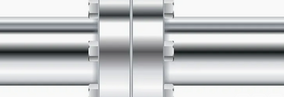
Four-bolt hydraulic flanges solve a packaging and load problem that becomes more difficult with large threaded connections. Instead of tightening one large fitting with high torque, the flange clamp transfers load through four smaller bolts around a sealed port. This can make hose-to-port and tube-to-component connections easier to assemble in confined mobile and industrial equipment.
The arrangement is dependable only when the flange head, port, clamp, O-ring, and bolts belong to the same specified system. Similar appearance is not enough. A mismatched pattern or improvised modification can leave the seal unevenly loaded and can place a lower-rated component into a more demanding circuit.
Why a flange changes the installation problem
Large-diameter threaded fittings require wrench clearance and substantial assembly torque. They can also be difficult to orient when the hose or tube must approach a component from a fixed direction. A four-bolt flange separates those functions. The flange head carries the fluid passage and O-ring; the clamp halves and bolts hold the head against a smooth port face.
Load is distributed around the connection rather than concentrated in one threaded body. Split clamps provide another practical advantage: a technician can loosen four bolts and remove a clamp half without rotating the hose assembly. This is helpful when the line is long, stiff, or trapped between other components.
Forged flange components are common because the process can provide strength and durability for demanding hydraulic service. SAE J518 and ISO 6162 define widely used four-bolt connection dimensions. The applicable standard, size, series, material, bolt requirement, and component manufacturer's rating must still be confirmed for the exact assembly.
Identify the series before a wrench is used
SAE Code 61 and Code 62 connections are not interchangeable. Their flange head dimensions, bolt patterns, clamp details, and pressure capabilities differ. Other manufacturer-specific four-bolt patterns can look close enough to cause a field mistake while remaining dimensionally incompatible.
Measure the port and flange head, then compare them with the correct dimensional table. Check the bolt spacing in both directions, flange head thickness and width, port size, O-ring groove, clamp marking, and bolt specification. Do not use the gap between holes as permission to force a part into place.
Pressure statements also require care. Code 62 is the higher-pressure SAE series, but one pressure value should not be applied across every size, material, configuration, or manufacturer's product. The assembly is limited by the lowest-rated flange head, clamp, bolts, port, adapter, hose, and other connected component.
A field modification can hide the real mismatch
A dangerous error begins when a replacement motor or valve arrives with a four-bolt port and the existing clamp almost fits. Enlarging, filing, or slotting clamp or bolt holes may allow bolts to enter, but it does not convert the flange series. The modified parts can pull the O-ring unevenly against the port and remove material from a load-carrying component.
The correct response is to stop and identify both sides. Determine whether the new component has a different series, whether the hose assembly contains the wrong flange head, or whether an approved transition is required. Document the equipment revision rather than making an undocumented field alteration that the next technician cannot recognize.
The same rule applies to substituting bolt grade, length, thread, or washer arrangements. Fasteners are part of the engineered joint. Replacing them by appearance can change thread engagement, clamp load, and clearance around the flange.
The O-ring seals; the bolts create the conditions for it
In a typical SAE-style connection, the O-ring sits in the flange-head groove and seals against the flat female port face. The clamp and bolts do not directly seal the fluid. They hold the two surfaces together with the alignment and compression needed for the O-ring to work.
Inspect the groove and port face for scratches, corrosion, embedded debris, and previous mechanical damage. Use the specified O-ring material and size for the fluid and temperature. An O-ring that is nicked during installation, twisted in the groove, or reused after flattening may leak even when bolt torque is correct.
Bring the flange head squarely to the port without using the bolts to pull a misrouted hose into alignment. A hose under side load can shift the flange during tightening and continue loading the joint during machine operation.
Cross-tightening controls clamp load
Start all four bolts by hand. Seat the clamp evenly, then tighten in stages using the specified cross pattern and final torque for the exact hardware. Alternating across the rectangular pattern reduces the chance that one side is fully compressed while the opposite side remains open.
Uneven tightening can leave some bolts loose and overload others. Over-compression may damage the O-ring or distort the clamp; insufficient clamp load can allow a gap to form during pressure and temperature cycles. Final inspection should confirm that the clamp halves are positioned correctly and that the gap, if specified by the component instructions, is even.
Do not rely on a universal torque number. Bolt size, grade, lubrication condition, plating, thread engagement, and the flange manufacturer's instructions all affect the required value. Record the procedure used when the connection is part of a controlled assembly or maintenance program.
Most leakage points back to parts or assembly
When a flange leaks, the O-ring is only one possible cause. A damaged flange face, wrong seal, loose or uneven bolts, line misalignment, and incorrect installation can all open a leakage path. Replacing the O-ring without inspecting the joint may produce only a temporary result.
A practical failure review asks four questions: Are all parts the correct series and size? Are the sealing surfaces undamaged and clean? Was the line aligned before tightening? Was the approved bolt sequence and torque process followed? Evidence at the joint often separates a component problem from an installation problem.
Four-bolt flanges are useful precisely because they provide a compact, serviceable connection for demanding hydraulic equipment. Their reliability comes from identification and controlled assembly, not from the fact that four bolts can be made to line up.