
Check Hydraulic Hose Bend Radius in the Installed Motion Envelope
Jul 2nd 2026
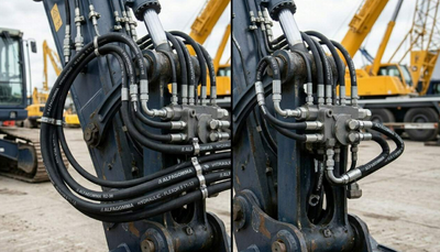
Minimum bend radius is a limit for a specific hose construction and size. It is not a target for making every route as tight as possible. An assembly that just meets the limit while parked may fall below it when a cylinder extends, a joint articulates, pressure changes the hose shape, or a clamp shifts the tangent point.
The correct review measures the installed hose through its full safe motion envelope and includes the transition next to each coupling.
Use the manufacturer’s radius definition
Hose data identifies the minimum radius at a specified reference, commonly related to the inside of the curve or hose centerline depending on the standard and manufacturer. Use the exact drawing or catalog definition rather than assuming where to place a ruler.
Radius is not bend diameter. A hose with a lower allowable radius can make a tighter curve; a “higher bend radius” does not mean more flexibility. Two hoses with the same outside diameter can have different limits because tube, reinforcement, braid or spiral construction, cover, and manufacturing design differ.
Do not calculate an installed radius from arc length and angle unless the hose forms a known circular arc and the measurement method matches the specification. Real routes often contain changing curvature and constrained ends.
Preserve a straight tangent near the fitting
The rigid coupling prevents the hose from distributing strain evenly. Bending immediately behind the ferrule concentrates flex at the hose-to-fitting transition and can fatigue reinforcement or loosen the assembly.
Manufacturer guidance may specify a minimum straight length or a relationship to hose diameter before the bend begins. A clamp or bend restrictor should support that design, not force a hinge at its edge.
Select elbow orientation so the hose leaves the fitting in the intended direction. Twisting the hose to reach a port changes how reinforcement carries pressure and motion.
Check every operating position
Define fixed and moving attachment points, then inspect extension, retraction, steering, rotation, suspension travel, and attachment changes using the safe machine procedure. Locate the position with the smallest radius, highest tension, greatest slack, and nearest pinch or rub point.
A route can alternate between being too tight and too loose. Additional length may relieve one position but create a loop that snags in another. Use guides, swivels, articulated routing devices, or revised end geometry only when qualified for the application.
Dynamic flex deserves a larger design margin than a one-time static bend. Cycle frequency, pressure impulse, temperature, and reinforcement construction influence fatigue.
A flattened bend changes flow and stress
Excessive curvature can ovalize or kink the hose, reducing internal area and disturbing reinforcement. The restriction increases local pressure loss and heat for a given flow, but the greater safety concern may be structural damage rather than system inefficiency.
Do not assume a relief valve will protect a kinked hose. Load-induced pressure and transients can still act on weakened reinforcement. A hose that has been forced below its allowable radius may require replacement even after the route is straightened; follow the manufacturer’s inspection criteria.
Routing components must not create new damage
Clamps control the path but can crush the cover or trap abrasive debris. Spiral guards and sleeves protect against contact but can hide a tight bend. A spring guard or molded restrictor can spread curvature near a fitting when it is designed for that assembly.
Keep the route clear of heat, sharp edges, moving structures, and surfaces that can transfer load to the fitting. Preserve access for inspection. Never use cable ties tightened so severely that they deform the hose.
Specify replacements by geometry as well as ends
Record cut length or overall assembly length using the hose supplier’s convention, fitting types, clocking or angular orientation, hose family, size, and protective components. A replacement with correct threads but different fitting drop length can alter the installed radius.
Before pressurization, confirm the route is untwisted and couplings are seated. After controlled operation, reinspect tangent areas, clamps, minimum-radius locations, and clearance.
There is no safe temporary arrangement that knowingly operates below the specified bend radius while waiting for a better hose. If the assembly cannot be routed within its limits, remove the machine from service or use an authorized repair disposition.
Minimum bend radius protects reinforcement and flow only when applied to the installed system. Manufacturer data, straight length at couplings, motion, support, and end geometry must agree in the machine position that places the greatest demand on the hose.