
Distinguish ISO Flange, Metric O-Ring Port, and Ferrule Tube Connections
HGW Hydraulics on May 4th 2021
ISO flange and port designations can appear beside instrumentation tube fittings in a fluid-power system, but they solve different connection problems. One clamps an O-ring at a flange face, one compresses an O-ring at a metric stud port, and one sets ferrules around tube.
Read ISO 6162 at the flange head
An ISO 6162-type connection includes a flanged head, O-ring groove, port face, clamp halves or a captive flange and four fasteners. The bolts create clamp load; fluid seals where the O-ring contacts the machined port.
Standard and high-pressure series often called Code 61 and Code 62 use different head and bolt-pattern dimensions. Pressure capability varies with nominal size and version, so do not attach one PN or bar value to every connection in a series.
Confirm fastener thread and grade from the port and equipment documentation. A marking can aid identification but should not replace measurement. Use the prescribed bolt sequence and final clamp-gap criteria.
Identify ISO 6149 by metric stud and port form
ISO 6149 uses a metric straight thread and an elastomeric boss seal. The port includes a controlled chamfer and spotface; the stud carries the O-ring and may include adjustable-position hardware.
This resembles an SAE ORB conceptually, but the metric thread, dimensions and port details differ. Measure pitch and inspect the chamfer. Protect the seal across the thread and orient adjustable bodies under their locknut procedure.
Treat double-ferrule fittings as a tube system
A double-ferrule instrumentation connection normally has a body, nut, front ferrule and back ferrule. The front ferrule forms the primary seal against the body while the rear element controls grip according to the design.
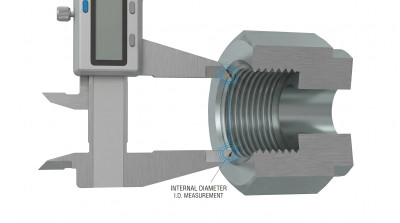
Tube outside diameter, wall, hardness, material and surface finish must meet the fitting instructions. Nut thread is an internal assembly feature and is not a reason to mix components across manufacturers.
Keep single-ferrule parts separate
A single-ferrule fitting uses one engineered element for its specified gripping and sealing behavior. It is not a double-ferrule body with the rear piece omitted. Assembly turns, gauges, tube requirements and remake rules belong to that system.
Brass and stainless are common body materials, but exact alloy, pressure, temperature and media still require verification.
Record the seal before ordering
For a flange, document code, head, bolt pattern and O-ring. For a metric port, capture thread, chamfer and stud style. For a tube fitting, record tube OD and wall, ferrule arrangement, material and opposite port.
These families can coexist on the same machine. Correct identification preserves each designed seal rather than grouping everything with an ISO or instrumentation label.