
Verify JIS Four-Bolt Flanges by Type, Pattern, Seal, and Fasteners
HGW Hydraulics on Feb 17th 2022
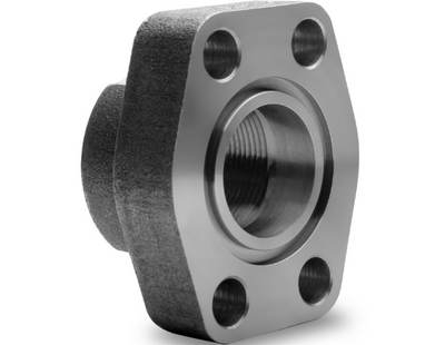
JIS four-bolt flange connections use a flanged head, an unthreaded port, an O-ring and four fasteners. That working principle resembles other hydraulic clamp flanges, but it does not authorize substitution from appearance.
Begin with the exact JIS designation and dimensional evidence, especially on older imported equipment.
Confirm Type I or Type II from dimensions
Field references commonly compare Type I with a standard-pressure flange family and Type II with a heavier-duty family. Use that comparison only to choose a candidate table.
Measure port, bolt spacing in two directions, flange-head diameter and thickness, groove and O-ring. Type II hardware and pattern details differ from Type I. Pressure requirement must be checked against the exact size and specification rather than inferred from the type name.
Follow the seal load path
The O-ring sits in the specified groove and is compressed against the port face. Clamps or a flange body transfer the bolt load to the head; the bolts do not seal the fluid through their threads.
Inspect groove edges, port flatness, corrosion and damage from a previously misaligned flange. Use the required O-ring dimensions and material. A seal that fits loosely in the groove is not necessarily correct.
Verify fasteners as part of the connection
Metric and inch screws can appear in related international flange systems. Threading a substitute screw into a hole does not prove property class, length, engagement or tightening method.
Record screw thread, length, grade or property class, clamp type and washer requirements. Use a complete compatible fastener set and the specified tightening sequence.
Check any proposed cross-standard replacement
JIS, ISO, SAE and former DIN flange references may overlap in selected dimensions. They should not be described as universally interchangeable. Compare the exact series, nominal size, bolt pattern, head, groove, seal and fasteners.
If a qualified adapter changes the machine port to another standard, document both interfaces and keep the conversion with the equipment record. Avoid mixing one standard's head with another standard's O-ring by habit.
Control installation alignment
Support the tube or hose so the flange head reaches the port without side load. Seat the O-ring cleanly, position clamps correctly and bring fasteners down evenly under the governing procedure.
After assembly, restore pressure safely and inspect from outside the possible spray path. A leak calls for depressurization and examination of the face, groove, seal and alignment rather than indiscriminate bolt tightening.
Type and pattern identify the candidate; seal and fastener details complete the JIS connection.