
JIS 4-Bolt Hydraulic Flanges: Type 1 and Type 2 Basics
HGW Hydraulics on Feb 17th 2022
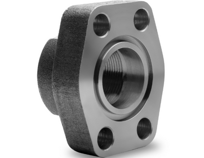
JIS 4-bolt flanges are used in fluid power systems and follow the same general connection idea as other four-bolt hydraulic flange styles. A male flanged head mates to an unthreaded port or flange face, and bolts hold the joint together.
The connection seals with an O-ring between the flange head and the flat surface around the port.
Basic JIS 4-Bolt Layout
The female side has an unthreaded port with four bolt holes at the corners. The male side has a flanged head with matching holes and a grooved recess for the O-ring.
During assembly, threaded bolts pass through the flange holes and secure the flange to a mating flange or to the flat port face. The O-ring compression creates the fluid seal.
Type 1 and Type 2
JIS 4-bolt flanges are commonly discussed in two pressure ratings. Type 1 is similar in application to SAE Code 61. Type 2 is the heavier-duty series and is similar in purpose to SAE Code 62.
Type 2 uses larger bolt head diameters and larger bolt diameters than Type 1. That extra capacity is part of why it is used for heavier service.
Interchangeability Notes
JIS B 8363 flanges are often compared with DIN 20066 and SAE J518 flange standards. In some cases, interchangeability is possible, but bolt type, bolt size, pressure class, and dimensional details must still be checked.
Both inch and metric bolts may appear in flange systems. The bolt pattern alone does not confirm the full standard.
Installation Checks
Inspect the O-ring groove, flange face, port face, bolts, clamp or flange hardware, and pressure class before installation. A damaged O-ring or uneven bolt loading can cause leaks even when the flange family is correct.
When replacing a JIS flange, confirm whether it is Type 1 or Type 2, then match the O-ring size, bolt dimensions, pressure rating, and mating surface.