
Diagnose Back Ferrule Damage from Tube Grip, Motion, and Assembly Evidence
HGW Hydraulics on Dec 24th 2024
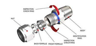
A back ferrule is one part of a precision tube-fitting system. Its exact job varies with the design, but it commonly contributes tube grip and load control while the front ferrule establishes the primary seal. Damage at the back ferrule is evidence to investigate, not proof that all dual-ferrule connections are unreliable.
Before replacing pieces, preserve the component order, tube location and operating history. Those details often reveal whether the fitting was assembled incorrectly or loaded by the surrounding installation.
Confirm that every component belongs to one system
Body, nut, front ferrule, back ferrule and tube dimensions must match the approved manufacturer and series. Similar-looking parts from different systems are not automatically interchangeable. Material, surface treatment and geometry can differ even when a nut threads onto the body.
Check the fitting designation, tube outside diameter and wall, material and hardness limits. Substitution can change how the ferrules move, grip and seal during pull-up.
Inspect tube preparation and insertion
The tube should be cut by an approved method, deburred without a heavy chamfer, cleaned and inserted fully against the fitting shoulder. Deep longitudinal scratches, ovality, dents, weld-bead problems or contamination can interfere with uniform ferrule contact.
Misalignment is another warning. Pulling an offset tube into place with the nut applies bending load before the system is pressurized. The assembly should meet naturally without using the fitting as a clamp to correct the route.
Reconstruct the ferrule-setting step
Verify ferrule orientation and component order. Determine whether the joint was assembled from finger tight, preset with a tool or reassembled from a previously set condition. Follow the fitting maker’s turn, gap-gauge or torque procedure for that exact state.
Under-assembly can leave inadequate grip or seal contact. Excessive pull-up may deform the tube, ferrules, nut or body. Marks from repeated wrenching can show that leakage was addressed by adding turns instead of finding the damaged interface.
Trace motion back to supports and routing
Pressure pulsation, equipment vibration and thermal movement can concentrate alternating stress close to a rigid joint. Inspect clamps, unsupported span, tube resonance, alignment and motion of the connected component. A support located or tightened incorrectly can also impose stress, so placement should follow the system design.
Fretting, polished contact bands or a fatigue crack can help distinguish cyclic motion from a one-time assembly mark. Correct the source of movement rather than simply installing a new ferrule in the same layout.
Separate corrosion from mechanical damage
External chemicals, internal fluid, condensation and dissimilar materials can attack the tube or fitting. Pitting beneath a ferrule changes the contact surface and can initiate leakage. Confirm the exact alloy and environment; “stainless” or “brass” alone is not a compatibility assessment.
Cleanliness also matters. Particles trapped at the sealing or gripping area can score components and create an uneven set.
Decide what may be reused
Do not mix new ferrules with a damaged body or assume a cut tube end can be reassembled indefinitely. Follow the product instructions for inspection, remake limits and replacement. If the tube is shortened, confirm that routing and insertion still meet requirements.
After correcting the cause, test from a safe position under the approved procedure and document the result. A defensible ferrule failure report links the observed damage to component identity, installation, tube condition and external loading instead of blaming the smallest visible part.