
Specify Compression Tube Fittings as a Matched Body, Ferrule, and Tube System
HGW Hydraulics on Jan 21st 2021
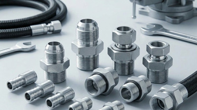
Compression and instrumentation tube fittings use a nut and one or more ferrules to grip unflared tube and create a pressure boundary. Their performance comes from the complete geometry and tube specification, not a general rule that two ferrules always handle more pressure than one.
Compare designs by their qualified system
A single-ferrule design uses one element to develop its specified grip and seal. A double-ferrule design divides functions between front and back pieces according to the manufacturer’s geometry. Other flareless systems use cutting rings, sleeves or preset components.
Pressure, vibration and temperature capability must be taken from the exact fitting and tube combination. Do not transfer turn counts, gap gauges or remake rules between brands because the parts look similar.
Treat the tube as a pressure component
Confirm outside diameter, wall, alloy, hardness, surface finish, ovality and weld condition. The tube must be strong enough for pressure yet suitable for the ferrule to set as designed. Deep scratches, dents, paint and an uneven cut can cross the sealing or gripping band.
Route the tube into the body without side load. Pulling an offset run into position with the nut leaves bending stress at the connection.
Select material from the actual media and environment
Brass serves many compatible water, pneumatic and instrument utilities. Carbon steel can suit protected industrial service where coating and fluid allow it. Stainless is common in corrosive, washdown or controlled-process environments.
Nickel-based and other specialty alloys may be required for defined chemical or temperature exposure. Trade families are not interchangeable, and no alloy name creates a universal 10,000 psi or 1,000-degree rating. Review exact grade, tube, fitting design and corrosion data.
Apply application-specific controls
Chemical and petrochemical sampling lines need wetted-material compatibility and low dead volume. Oil and gas panels add outdoor exposure, vibration and project documentation. Medical or pharmaceutical equipment may require cleanliness, traceability and process-contact controls.
Power and aerospace uses are governed by their equipment, code and approved-source requirements. Gas and CNG installations have code, accessibility, joining and testing rules that cannot be reduced to “use brass above ground” or generic PTFE tape advice.
Bulkhead fittings support tube through panels and instrument enclosures. Their mounting thread, locknut, clearance and tube alignment must be distinguished from the tube-end seal. Gauge and valve panels also need room to hold the fitting body while pulling up the nut.
Cryogenic or very hot service changes tube contraction, material toughness and seal behavior. Use the complete qualified system and procedure for that temperature; a room-temperature compression fitting description is not approval.
For toxic, flammable or high-purity media, define leakage acceptance, cleaning, material traceability and testing before installation. Accessible service may remain a code requirement even when the fitting itself is technically capable.
Assemble under the instructions for that size and state
Cut squarely, deburr without changing the intended edge, clean and insert fully to the shoulder. Bring the nut to the specified starting position, stabilize the body and apply the instructed turns, torque, preset or gauge method.
Small and large sizes may use different procedures. Presetting tools and inspection gauges are product-specific. On a remake, follow the defined method for ferrules already set on the same tube; do not transfer used ferrules to a new end.
Marking the nut provides a visible reference, but the starting condition must be correct. Finger-tight can be affected by dirt, damaged threads or a tube that has not reached the shoulder. Stop if resistance appears before full insertion.
After pull-up, do not rotate the body to correct orientation unless the system permits it. Use a backup wrench and design the route so tube does not wind up. Protect open ends from particles while the circuit is incomplete.
Investigate leakage without adding turns blindly
After safe isolation, inspect component identity, tube insertion, ferrule orientation, face condition, corrosion, vibration and alignment. Over-pull-up can deform tube and fitting, while under-assembly may leave insufficient contact.
Do not mix bodies, nuts and ferrules from different makers unless documented compatibility exists. If a new tube end requires cutting back, confirm the remaining length and support.
Return-to-service checks should be staged at the required pressure from a safe location. Use an approved leak-detection method and record whether the connection is a first assembly or remake. A leak-free bench condition does not validate vibration, thermal cycling or a tube forced into place.
Retain the failed ferrules and tube section when a recurring problem is investigated. Contact bands, scoring and fretting can reveal incomplete insertion, motion or over-assembly that would be lost if only the fitting body were examined.
Compression fittings support industries from laboratories to power equipment because they create serviceable tube connections. Reliability comes from preserving one matched system and its procedure from order through installation.