
Size Hydraulic Lines from Flow, Velocity, Pressure Loss, and Machine Duty
HGW Hydraulics on Dec 13th 2023
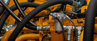
Hydraulic line sizing is an energy and reliability decision. A passage that is too small can increase velocity, pressure loss, noise, and heat. A line that is larger than needed can add fluid volume, mass, cost, and slow response. The final choice must account for flow, viscosity, duty, component losses, routing, pressure, and the machine manufacturer’s limits.
Use velocity as an initial screen
For a known volumetric flow, average velocity can be estimated from internal flow area. In U.S. customary units:
`V = 0.3208 × Q / A`
where `V` is feet per second, `Q` is gallons per minute, and `A` is internal area in square inches. For a circular bore, `A = 0.7854 × D²`, with inside diameter `D` in inches. Rearranging gives `D = √(0.4085 × Q / V)`.
At 10 gpm and a screening velocity of 20 ft/s, the calculated ideal bore is about 0.452 inch. That result is not automatically a one-half-inch pipe or hose selection: nominal pipe size, tube OD and wall, and hose dash size use different naming, and the actual inside diameter must be checked.
Common rules of thumb often keep suction velocity lowest, return velocity moderate, and pressure-line velocity higher. Values quoted for another aircraft, machine, fluid, or duty are not universal design limits. Pump inlet requirements, oil viscosity, line length, elevation, acceleration, and OEM data can demand a different target.
Calculate pressure loss through the whole path
Velocity alone does not predict the complete loss. Line length, internal roughness, viscosity and temperature, bends, tees, adapters, valves, quick couplings, filters, coolers, and entrance or exit geometry all contribute. A nominally adequate hose can still create excess loss through restrictive end fittings.
For a pump inlet, available absolute pressure and the pump manufacturer’s inlet requirement are critical. Excess suction restriction can contribute to cavitation, noise, poor filling, and damage. A case-drain line may have a strict maximum backpressure even though its flow is relatively small. Return lines also need evaluation for cold oil and filter loading.
Select rigid line and hose by motion
Tube or pipe is useful along fixed, supported routes. Hose belongs where components move, vibration needs isolation, or service access requires flexibility. Mark the machine’s full range of travel and choose the boundary between rigid and flexible sections deliberately.
For hose, check inside diameter, minimum bend radius, length change under pressure, straight length near couplings, torsion, abrasion, clamps, and heat. A layline can help reveal twist after the hose is identified, but it should not be the only source for selecting a replacement.
For tube, verify outside diameter, wall thickness, material, bend quality, supports, and fitting system. Do not use a connector to pull misaligned rigid lines together.
Match pressure, temperature, and media at assembly level
Normal pressure, relief setting, surge, impulse duty, vacuum, and temperature must be within the finished line and connector ratings. Hose, fittings, adapters, ports, seals, tube, and clamps all participate. Burst pressure is not a working target.
Fluid compatibility covers hose tube and cover, pipe or tube material, plating, O-rings, and external chemicals. Hot oil reduces viscosity and can change loss while also aging elastomers; cold oil can sharply increase suction and return restrictions.
Choose connectors by seal and flow geometry
JIC and other metal-flare connections seal at mating cones. ORB and ORFS use elastomeric seals at boss or face locations. NPT and other pipe threads use different retention and sealing logic. Identify the connection before evaluating its bore.
Elbows, reducers, swivels, and quick couplings can be necessary for routing and service, but their internal passages and turns may add loss. Compare the actual component data, especially where several adapters are stacked or high flow passes through a small nominal connection.
Tighten by the applicable instruction. Over-tightening can crack tapered ports, damage flare seats, or extrude O-rings without increasing allowable pressure. Support lines so vibration and weight do not act through the connector.
Verify the design under its worst operating mode
Review cold start, maximum commanded flow, simultaneous actuator movement, cylinder regeneration, attachment changes, filter loading, and the highest duty cycle. Measure pressure and temperature at useful points when the risk justifies it. A line may pass a no-load shop check and still overheat or starve the pump in production.
Document calculated flow, selected ID, expected velocity, pressure-loss method, component data, hose or tube specification, connections, routing, and approval. That record allows later repairs to preserve the hydraulic design instead of replacing a line with the closest outside diameter.