
Instrumentation Valve Selection by Function, Isolation Plan, and Process Conditions
HGW Hydraulics on Jan 18th 2024
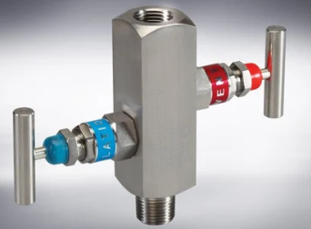
Instrumentation valves do more than open and close a small line. They isolate instruments, meter samples, prevent reverse flow, route test connections, and create controlled bleed paths. The right valve begins with the process function and failure consequence, then moves to materials, sealing, actuation, and port details.
A catalog pressure value cannot replace this system definition. Pressure fluctuation, temperature, media, flow coefficient, orifice, applicable codes, packing design, and maintenance access can each change the selection.
Define what the valve must do in every operating state
List normal flow direction, open and closed states, required isolation, vent or drain destination, and behavior during startup, shutdown, testing, and maintenance. Determine whether the operator needs simple on/off action, fine metering, automatic reverse-flow prevention, or redundant isolation.
Also identify whether the valve will be manually operated or actuated. Pneumatic, electric, or other actuators need compatible torque, control signal, fail position, environmental protection, and feedback. An actuator does not correct an undersized or incompatible valve body.
Ball valves provide rapid isolation and routing
A ball valve rotates a bored sphere, commonly through a quarter turn. When the bore aligns with the passage, flow is open; turning it across the passage closes the route. Two-way, angle, and multiport arrangements can isolate or redirect a line.
Ball valves are useful where fast, visible shutoff is needed. They are not normally chosen for precise throttling unless the specific design supports it. Seat and packing materials, bore style, cycle frequency, trapped-cavity behavior, pressure direction, and actuator load must be checked from product data.
Needle valves meter through a tapered stem
A needle valve moves a tapered stem toward or away from a small seat. Multiple turns allow controlled changes in opening, making the design useful for sampling, instrument isolation with controlled equalization, and low-flow adjustment.
Fine control depends on stem profile, orifice, fluid properties, pressure drop, and valve range. The handle position is not a calibrated flow measurement unless the product is designed and characterized for that use. Bonnet, packing, stem tip, and seat materials must suit temperature and media.
Check valves respond automatically to differential pressure
A check valve allows intended forward flow and closes when pressure reverses. Spring, poppet, ball, or other mechanisms create a defined cracking condition. Cracking pressure, reseal behavior, flow capacity, orientation, contamination sensitivity, and backpressure matter.
“One-way” does not mean zero leakage under every condition. If reverse leakage is critical, specify the allowable rate and test method. Small instrument check valves can be especially sensitive to particles at the seat.
Double-block-and-bleed controls isolation boundaries
A double-block-and-bleed arrangement combines two isolation elements with a bleed or vent between them. The intermediate path can reveal leakage past the first barrier and relieve trapped pressure under the defined operating procedure.
Terminology and code requirements vary by industry. Confirm whether the application requires double block and bleed, double isolation and bleed, or another isolation philosophy. Valve cavity, bleed routing, hazardous media handling, and safe work procedures must be engineered; a compact body does not by itself prove the required isolation level.
Manifolds organize instrument connections
Two-, three-, and five-valve manifolds can place isolation, equalizing, test, drain, and vent functions in one block. Pressure gauges, switches, and differential-pressure transmitters use different arrangements. A manifold can reduce separate fittings and leak points while improving service access.
Port standards may include NPT, metric, ORB, flange, or manufacturer-specific interfaces. The block material, stem and seat design, packing location, process connection, instrument connection, mounting, and flow schematic must all match the installation.
Packing and materials follow media and temperature
Packing limits leakage along the moving stem. PTFE-family materials, engineered polymers, graphite-based packing, soft seats, and metal seats each have defined temperature, chemical, friction, and emissions behavior. Use the valve manufacturer’s validated limits rather than a generic temperature band.
316 stainless steel, carbon steel, nickel alloys, titanium, and other materials serve different corrosion and mechanical conditions. Sour service, oxygen, high-purity, fire-safe, low-emission, and sanitary applications may invoke specific material and code requirements.
Close the specification with flow and proof
Calculate or verify required flow coefficient and allowable pressure drop. Check maximum and minimum pressure, differential pressure at operation, temperature cycles, media state, solids, viscosity, and flashing or cavitation potential. Define tests, inspection, traceability, cleanliness, and certification only where the application requires them.
Finally, review the piping and maintenance procedure. Operators need enough access to actuate, lock, vent, drain, and replace the valve without unsafe exposure.
Instrumentation valve selection is reliable when the isolation diagram and process conditions lead the decision. Ball, needle, check, DBB, and manifold designs are tools for different functions; their names are the beginning of the specification, not the end.