
Select a Solenoid Valve from Its De-Energized State and Pressure Differential
HGW Hydraulics on Jul 22nd 2026
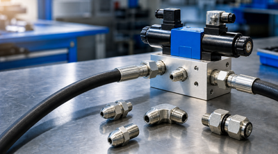
A solenoid valve combines an electromagnetic operator with a fluid-control element. An electrical command moves an armature or plunger, which directly changes a seat or pilots a larger valve stage. The first selection question is what flow path the valve must create when power is absent.
Draw the normal and energized flow paths
“Normally closed” means the specified passage is blocked in the de-energized state; “normally open” means it is available. A two-way valve controls one flow path, while a three-way or directional design connects and exhausts or redirects ports according to its symbol.
Normal state should support the machine’s fail-safe analysis, but a valve label alone does not guarantee safety. Stored pressure, gravity loads, spring return, trapped fluid and controller logic determine what the equipment actually does after power loss.
Decide between direct and pilot operation
A direct-acting valve uses magnetic force to move the main sealing element. It can operate with little or no pressure differential, though flow capacity and orifice size are constrained by available coil force.
A pilot-operated valve controls a small passage so fluid pressure helps shift the main element. This can support larger flows, but the valve may require a minimum pressure difference, correct flow direction and clear pilot passages. A pilot valve selected for a near-zero differential circuit may fail to open or close as expected.
Treat coil and plunger as different design problems
The coil must match voltage, AC or DC supply, allowable variation, duty cycle, ambient temperature, connector and enclosure. Inrush, holding current and heat dissipation can matter. Twelve volts is one option, not a universal solenoid supply.
The plunger or armature needs a clean guided path and sufficient magnetic force across its stroke. Springs, residual magnetism, friction and contamination affect response. The valve body contains the pressure boundary, ports, seats and seals; it is not merely a housing for the electrical parts.
Size flow with pressure loss and media properties
Use required flow, allowable pressure drop and the product’s flow coefficient or performance curve. Port thread alone does not establish capacity. Gas and liquid calculations differ, and fluid viscosity can reduce flow through small hydraulic passages.
Check minimum, normal and maximum inlet and outlet pressure, differential across the valve, reverse pressure and credible transients. A general claim such as “up to 1,200 psi” cannot be applied across sizes and constructions.
Response time also depends on pressure, coil force, moving mass, spring, viscosity and controller switching. Opening and closing times can differ. If timing affects a cylinder sequence or dosing function, use verified dynamic data and measure the complete installed circuit.
A modulating or proportional solenoid valve is not the same as a simple on/off device. It requires compatible electronics, command range, hysteresis and flow-performance review. Do not assume every plunger valve can regulate continuously between open and closed.
Match every wetted material
Body, seat, diaphragm, O-rings, plunger tube and springs can contact the media. Air, water, steam, fuel, chemicals and hydraulic oil require different combinations. Temperature at the valve includes both fluid heat and coil self-heating.
Particles can hold a seat open or block a pilot orifice. Define filtration and cleanliness without adding a filter that creates unacceptable pressure loss.
Integrate electrical protection and controls
Confirm grounding, fuse or circuit protection, switching capacity and suppression for inductive voltage where required. A diode is polarity-sensitive and can slow release in some DC circuits; other suppression methods behave differently. Follow the controller and valve instructions.
Hazardous locations, washdown, outdoor exposure and vibration may require certified enclosures, connectors or cable entries. Do not infer an environmental rating from a molded coil alone.
Coil duty may be continuous, intermittent or time-limited. Evaluate the hottest credible fluid and ambient condition because electrical heating adds to both. Mounting near other energized coils or inside an unventilated enclosure can raise temperature above a bench-test condition.
Control logic should detect or tolerate open circuits, shorts and unexpected valve state as required by the risk assessment. Position feedback is separate hardware; energizing a coil proves a command was sent, not that the fluid path moved.
Verify mounting, ports, and manual features
Threaded inline bodies, cartridge valves and manifold-mounted valves have different cavities, seals and installation torque. Match port standard, flow direction and manifold interface. A cartridge with a similar diameter may have another nose geometry or pilot path.
Some valves include a manual override for setup or emergency procedure. Its detent, momentary behavior and permitted use need clear instructions. An engaged override can make a correct electrical test appear to fail or can move equipment unexpectedly during maintenance.
Orient and support the valve according to its data. Pipe strain, hose side load or an unsupported coil connector can distort the body or damage wiring. Provide access to replace the coil without opening the fluid boundary where the design permits it.
Diagnose electrical and fluid sides separately
If the valve does not shift, verify command, voltage at the coil under load, connector, resistance or current and permissible coil temperature. Then check pressure differential, direction, pilot path and mechanical contamination under safe isolation.
Buzzing, heat, slow response and leakage have multiple causes. Low AC voltage, a blocked plunger, excessive cycling, wrong media, damaged seat or inadequate differential can look similar. Capture the state and measurements before replacing the valve.
Internal leakage across a seat should be distinguished from external leakage at a port, body joint or operator tube. A valve that shifts but produces weak actuator motion may be undersized, installed backward, pilot-starved or part of a broader pump and relief problem.
After replacement, verify normal and energized flow, de-energized fail state, leak condition, coil temperature and machine timing. Record the exact coil and valve body because some operators fit physically while having different voltage or duty.
The correct solenoid valve is defined by its schematic function, de-energized state, fluid performance and electrical environment together. Outside appearance and port size are only the beginning.